
Start with the chamber and its gas load, then select the pump and the connecting path. A vacuum system is more than a pump catalogue number: the achievable pressure and evacuation time depend on the chamber, process, line conductance, seals, valves, controls and test conditions.
Define the duty
- Chamber volume, target pressure and required evacuation time.
- Gas composition, vapour and particle load, and process cycle.
- Cleanliness and oil-contamination limits.
- Available power, cooling and heat removal.
- Control interfaces, interlocks and maintenance access.
Use these inputs to compare dry, rotary-vane, booster and turbomolecular arrangements. The nominal pumping speed at a pump inlet is not the effective speed at the chamber.
Match the pump train
For turbomolecular and high-vacuum systems, verify the permitted backing pressure, gas throughput, backing-pump capacity, controller and interlocks. CBVAC SSH20, JZB, JFB and MTP designate different products or families; their controllers, operating ranges and installation requirements are not interchangeable.
Specify how the chamber will be isolated, vented and protected during start-up, shutdown and power loss. Match the pressure sensors and control signals to these operating states.
Build a traceable bill of materials
| Assembly | Specification to record |
|---|---|
| Flanges and fittings | KF, ISO-K, ISO-F or CF; exact size, material and part number |
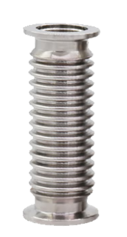
| Bellows | End connections, length, movement allowance and supports |
| Valve | Isolation or regulation function, drive, fail state, seal and interface |
| Gauge | Measurement principle, range, gas dependence, port and output |
| Pumps and controls | Complete model, backing requirements, cooling, controller and interlocks |
The Russian component catalogue identifies 569 CBVAC component stock-keeping units. Use the exact order code and drawing to select an execution. A series photograph illustrates construction; it does not establish the flange size, material, drive or supplied accessories of every item.
Assembly, leak testing and acceptance
Keep the vacuum path clean and mechanically supported. Check sealing surfaces, mounting instructions and access for maintenance before final assembly. Measure the pressure-time curve with the relevant valve positions, gas load and pumping arrangement documented. Investigate conductance restrictions and background gas before interpreting a slow pump-down as a leak.
Leak-test the assembled system with a suitable method, reference leak and verified response time. Record the pressure, background, detector settings and acceptance criterion. Confirm instrument calibration and the supplied documentation for the actual equipment.
Prepare an enquiry
Send a system sketch, process conditions, chamber volume, pressure target, cycle time and existing equipment model numbers. For spare parts, add the serial number, part marking and photographs of the interfaces. State the required scope: equipment only, matched components, installation or commissioning.
CBVAC catalogue · Warehouse stock · Engineering calculators · Discuss a configuration