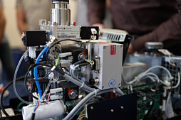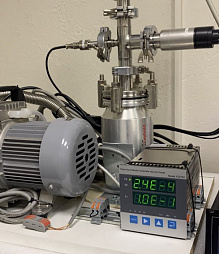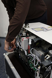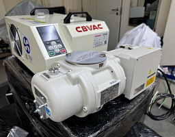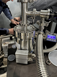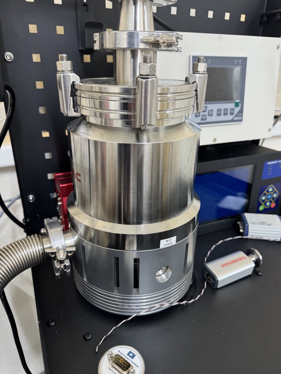
Project-configured vacuum system for evacuating up to six 40 L gas cylinders before filling. The source configuration combines a 6 L/s two-stage rotary-vane pump, vacuum measurement, isolation hardware and a heated cylinder cabinet. Final design, cleanliness target and safety controls must be validated for the gas, cylinders and filling process.
Description
Vacuum Evacuation System for Six Gas Cylinders
This project-configured system prepares gas cylinders for filling by removing residual gas, moisture and part of the surface load under vacuum. The source concept accommodates up to six 40 L cylinders and combines a heated cabinet, vacuum manifold, isolation components, pressure measurement and a two-stage rotary-vane pump.
Source Project Configuration
| Cylinder capacity | Up to six 40 L cylinders |
|---|---|
| Project evacuation target | Below 100 Pa; the required acceptance value must be established for the actual process |
| Cabinet heating | Up to 200 °C in the source concept, subject to the permitted temperature of each cylinder, valve, seal and accessory |
| Vacuum pump | Two-stage rotary-vane pump |
| Nominal pumping speed | 6 L/s (21.6 m³/h) |
| Pump ultimate pressure | ≤6 × 10⁻² Pa under the stated test conditions |
| Motor | 0.75 kW, approximately 1,400 rpm, 220 V supply in the source configuration |
| Pump dimensions and weight | Approximately 565 × 200 × 342 mm; 50 kg |
| Pump oil charge | Approximately 2 L |
| Vacuum connections | KF25 pump line with KF25/KF16 distribution components in the source configuration |
| Vacuum measurement | Pirani gauge with controller/power unit |
Typical Included Vacuum Hardware
- Oil-mist filter for the rotary-vane pump exhaust
- Pirani vacuum gauge and matching controller
- Approximately 1 m KF25 flexible bellows hose
- KF25 vacuum isolation valve
- Two KF25/KF16 tee fittings
- Five KF25 and one KF16 centering-ring/clamp sets with FKM seals
The manifold, cabinet, cold trap or moisture-control stage, cylinder connections, gauges, valves, electrical controls and interlocks are selected for the actual process. The final bill of materials, materials of construction, piping size, documentation language and acceptance testing are agreed during engineering.
Purity and Process Engineering
Residual-pressure dilution alone does not guarantee a finished-gas purity grade. The result also depends on cylinder desorption, leaks, trapped volumes, valve cleanliness, purge and backfill sequence, tracer or product-gas purity, moisture and oxygen limits, and the filling procedure. The evacuation endpoint and number of purge cycles must therefore be validated against a defined analytical acceptance criterion.
Safety
Cylinder evacuation, heating and high-pressure filling must be performed only by trained personnel using an approved process. The cylinder and valve manufacturer's temperature limits take precedence over the cabinet capability. The installation requires pressure-rated connections, protected heating, temperature and vacuum interlocks, safe exhaust routing, suitable ventilation, electrical protection, and compliance with all pressure-vessel, compressed-gas and site rules applicable in the destination country. A project hazard review is required before operation.
This page describes a configurable engineering system, not a guaranteed off-the-shelf purity result. Final specifications and supply scope are issued for the customer's cylinders, gas, pressure, target purity, cycle time and regulatory location.